1. Introduction
2. What will we inverse engineer (hack)?
2.1 REV device #1
2.2 Motion detection sensor
2.3 REV device #2
3. Conclusion and next steps
Introduction
Try to search for “433 MHz sensors” or “220V Remote Control Socket” in eBay and you’ll get a list of available
sensors broadcasting their data on 433 MHz frequency. Mostly this products are really cheap and affordable
for any type of family. There are two types of devices – sensors and power appliances.
Sensors (randomly selected from eBay search)
1. Magnetic – Detecting opening doors or windows.
2. Motion detector – working on heat signature.
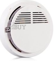
3. Smoke detector.
4. Water leak detector.
5. Gas detector.
And more ….
Power appliances (randomly selected from eBay search)
1. Curtain controller.
2. 220V wall power socket.
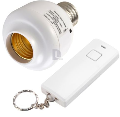
3. E27 Screw Bulb Lamp Socket.
4. E27 10M Screw Wireless Remote Control Light Lamp Bulb
And much more …
433 MHz frequency is totally legitimate in Europe, therefore European companies also create their own power
appliances and sensors based on this free, mostly non secured frequency.
What will we inverse engineer (hack)?
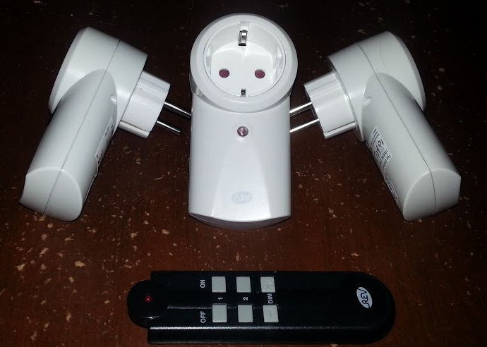
REV device #1
While I was on a business trip in Munich I came across a nice power wall socket kit sold in Saturn electronics
market. This socket manufactured by REV company (www.rev.biz) and is very solid built and quiet, no Chinese
manufacturer can compete with this product.
The best thing about this product is that you can control the final amount of devices (no learning system).
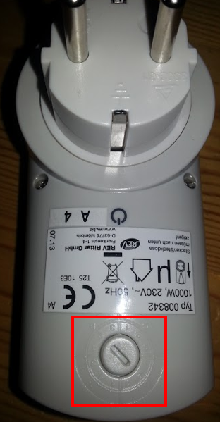
On the back of the remote there is group switch (A, B, C and D) so when you select “A” group you control the
devices that belong to this group. And on the back of the device there is a switch which allows to associate the
device with one of the groups.
So the amount of commands is final, has a total of 24 commands (therefore no need to build a learning system
means it’s easier to hack).
4 (groups) * 3 (devices for each group) * 2 (on and off)
Steps
The most important tool in this tutorial is Logic Analyzer (LA), if you don’t have one it will be pretty difficult to
find out what are the commands. Of course you can just use Arduino with 433 MHz receiver and with the spec
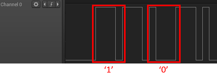
of the chip you can find out the SYNC, PAUSE, ‘1’ and ‘0’ signals. With LA it will be much faster and simpler.
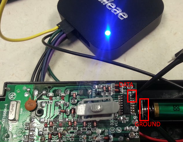
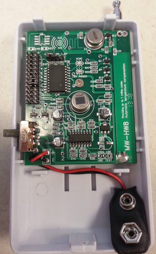
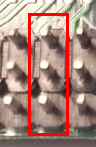
So first we need to understand how onboard chip is generating the commands when clicking on one of the
remote control buttons. Opening the remote reveals the PCB and the chip on it. I don’t know if it was on
purpose, but the top of the chip was scratched and I couldn’t read the chip name and manufacturer.
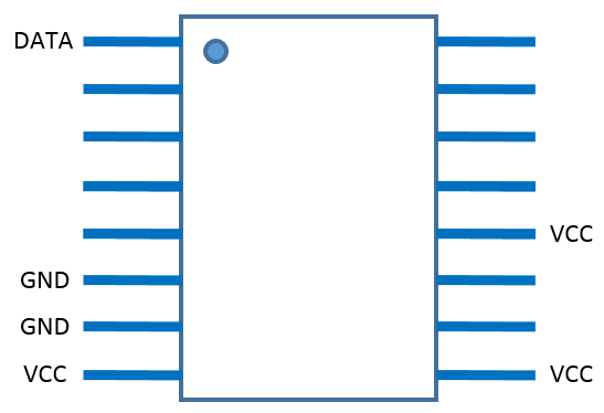
This makes it a bit difficult to figure out where the data pin on this chip is, so let’s just filter pin by pin.
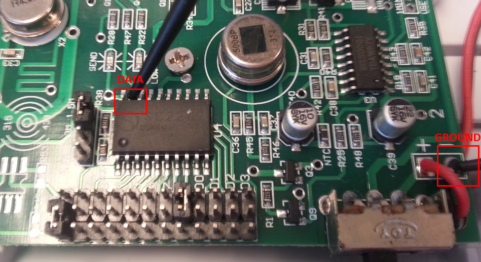
I connected the LA ground pin to the battery minus connector and the data pin to the chips’ pin, then I powered
the LA on and clicked on one of the buttons on the remote control. If LA printed something like bunch of HIGH
and LOW levels that means the selected pin is data.
The important data pin was found on pin 10 and ground on pin 16, for ground you can always use the battery
minus connector.
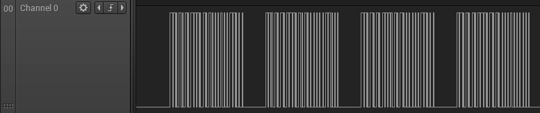
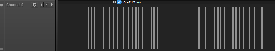
So after we figured out what is where, we can start recording the commands. ☺
Select group and click on each button.
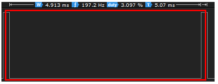
From the command we can clearly see that there are no SYNC commands (preamble) for each start of command.
Also we can see that each command is separated with PAUSE pulse.
Each output generated by LA saved as CSV file for later steps. After we saved the exported data to CSV format we can easily
generate the codes from the data.
This table describes when there was RISE/FALL (1/0).
I created a simple python script which will return just one integer that will represent a command.
The command eventually consist of 3 bytes (24 bits). Many Chinese devices work with the same pattern.
The Python code:
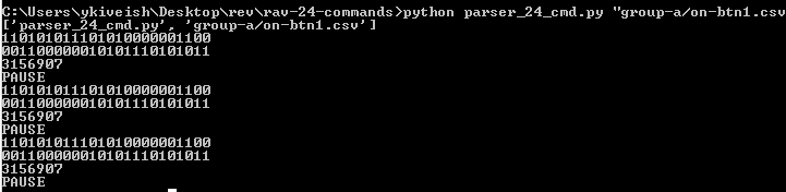
Example of one of the commands is bellow (python parser_24_cmd.py "group-a/on-btn1.csv") …
The output is 3156907 represented in binary 110101011101010000001100, for my understanding and simple
analysis the command represents GROUP ID, SWITCH ID and COMMAND (ON/OFF/DIM).
11010101 11010100 00001100
GROUP ID – SWITCH ID – COMMAND (ON/OFF/DIM)
ON/DIM_UP – 00000011
OFF/DIM_DOWN – 00001100
I recorded all the commands.
Group A
Button
|
command
|
Base 10
|
Base 2
|
BTN 1
|
ON
|
3156907
|
11010101 11010100 00001100
|
BTN 1
|
OFF
|
12594091
|
11010101 11010100 00000011
|
BTN 2
|
ON
|
3157675
|
11010101 01110100 00001100
|
BTN 2
|
OFF
|
12594859
|
11010101 01110100 00000011
|
BTN DIM
|
UP
|
3205803
|
11010101 01010111 00001100
|
BTN DIM
|
DOWN
|
12642987
|
11010101 01010111 00000011
|
Group B
Button
|
command
|
Base 10
|
Base 2
|
BTN 1
|
ON
|
3156910
|
01110101 11010100 00001100
|
BTN 1
|
OFF
|
12594094
|
01110101 11010100 00000011
|
BTN 2
|
ON
|
3157678
|
01110101 01110100 00001100
|
BTN 2
|
OFF
|
12594862
|
01110101 01110100 00000011
|
BTN DIM
|
UP
|
3205806
|
01110101 01010111 00001100
|
BTN DIM
|
DOWN
|
12642990
|
01110101 01010111 00000011
|
Group C
Button
|
command
|
Base 10
|
Base 2
|
BTN 1
|
ON
|
3156922
|
01011101 11010100 00001100
|
BTN 1
|
OFF
|
12594106
|
01011101 11010100 00000011
|
BTN 2
|
ON
|
3157690
|
01011101 01110100 00001100
|
BTN 2
|
OFF
|
12594874
|
01011101 01110100 00000011
|
BTN DIM
|
UP
|
3205818
|
01011101 01010111 00001100
|
BTN DIM
|
DOWN
|
12643002
|
01011101 01010111 00000011
|
Group D
Button
|
command
|
Base 10
|
Base 2
|
BTN 1
|
ON
|
3156970
|
01010111 11010100 00001100
|
BTN 1
|
OFF
|
12594154
|
01010111 11010100 00000011
|
BTN 2
|
ON
|
3157738
|
01010111 01110100 00001100
|
BTN 2
|
OFF
|
12594922
|
01010111 01110100 00000011
|
BTN DIM
|
UP
|
3205866
|
01010111 01010111 00001100
|
BTN DIM
|
DOWN
|
12643050
|
01010111 01010111 00000011
|
I wrote a simple code for Arduino that repeatedly turns on/off switch number one in group A (Arduino example “Blink”).
You’ll need to buy a cheap 433MHz transmitter for this to work.
The code for Arduino ….
That’s it, have fun hacking other devices.
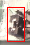
Motion detection sensor
This product made by Chinese unknown company and is very cheap, around 7$ on eBay. Powered by 9V battery.
Logic analyzer connections to the SC2262 encoder chip …
Each sensor has 8bit address, this address is configured using on board jumpers.
‘01’ ‘00’ ‘11’
The image above shows how the address will be represented in the transmitted command.
Command is built of 24bits. First 16bits represent the address, 2bits for each jumper selection (‘00’, ‘11’ and ‘01’).
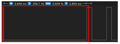
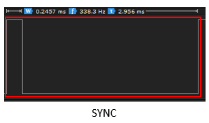
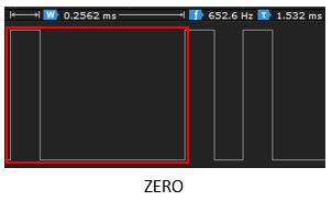
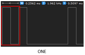
Signals decoding …
SYNC
‘0’
‘1’
PAUSE
That’s it for this sensor you’re more than welcome to develop your own sniffer (I’ll do it anyway for ALL the
433MHz devices) or you can use limited library for Arduino called RCSwitch.
REV device #2
This one is little bit harder to work with because each remote control has a different set of commands from
the remote control in another set of the same product. The devices have a button and when holding the button
for 3 seconds it will enter into “learning” mode. When the device in “learning” mode you need to press on one
of the ON buttons on the remote which will associate the device with the switch control. The device can have
more than one association.
In this case we’ll need to learn the protocol (which is very different from the protocol of the first device) and
make our own commands and send them to the device. Or we can build a sniffer and learn the commands
from the remote and use them to associate our Arduino/Edison/RPI with the devices.
The remote is based on a different chip, below are the important pins.
I already decoded the signals. The command is built of 64bits and starts from SYNC bit (preamble).
Conclusion and next steps
Current status
Currently I’m writing code that will sniff and decode (learn) the commands for the products in this document.
Also I continue looking for other devices with different encoders. I need many devices with different encoders
so I’ll be able to build a library to support various devices.
Future
I want to create a library which will run on Arduino and Linux platforms hosted on RPI and Edison. There are
some libraries that do almost the same, but there is no existing library that supports any existing decoding and
has an easy way to add new ones.